.jpg)
.jpg)
.jpg)
.jpg)
.jpg)
.jpg)
.jpg)
.jpg)
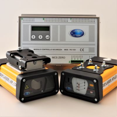
The MCS + DSP LASER AP safety device is a system that alone contributes to the protection of the operator when using press brakes for cold metal working and is made up of:
MCS and DSP LASER AP is the result of over thirty years of experience that Nuova Elettronica Pasqui has acquired in the field of safety for press brakes.
This system combines compliance with current regulations with practicality of installation, ease of use, speed of the bending cycle in an incredible relationship between quality-performance and cost.
MCS has been on the market since 2012 and has the task of controlling all the safety of the press brake through the programming, which can be done simply via PC or on the machine, of over twenty parameters.
In the standard version, MCS allows the speed change point to be reduced to 2mm, while today with the MCS ZERO version this space becomes zero!
The time saved with a DSP LASER AP compared to a conventional system is approximately 1.2 seconds for each fold, which with an average use of the machine allows you to save ONE MONTH OF WORK EVERY YEAR!
The transmitter generates the emission of a modulated visible laser light which, by affecting the receiver, creates a detection area and causes the latter to activate the transition to the ON state of the two OSSDs. It is underlined that the activation of the receiver is made possible only by the emission generated by the transmitter to which it is electrically connected.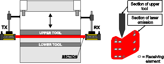
Not during all the phases of the machine cycle or in the different operating modalities, all the receivers are necessarily enabled to detect an object entering the detection area. To be detected, the object has to interrupt the laser beams hitting at least, one of the enabled sensors. Detecting the object causes the intervention of the device, which must stop the movement of the machine or activate an action foreseen by the operating cycle, as the inhibition of a set of sensors in case of blanking.
The horizontal protection layer is located from the tip of the tool at a safety distance equal to the maximum stop distance allowed for the safe use of the press brake with the DSP LASER AP device + 5mm. The maximum allowed values are, as described later, three: 14mm, 18mm and 24mm.
With the use of DSP LASER APLD device, the maximum allowed values are 14mm and 18mm.
The safety area pre-empts the movement of the upper tool for such a distance which allows stopping the tool without this can squash any opaque object possibly between itself and the lower tool.
The object possibly under the protection area, once penetrated it, should generate the command to stop the machine, which will stop within a distance called “machine stop distance”.
As the stop command has been generated at a distance equal to “maximum allowed stop distance” + 5mm, the tool has ended its movement at a distance = maximum allowed SA – machine SA + 5mm, clearly without even brushing on the object.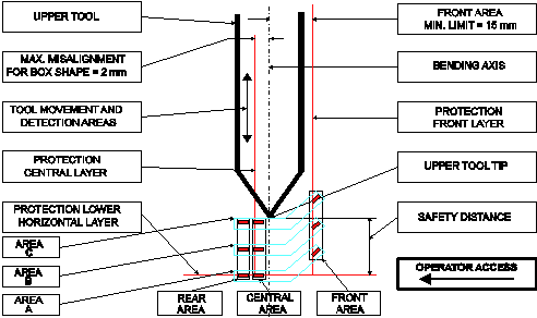
As regards the Blanking function used for bending boxes, the detection area is subdivided in 3 different areas: a front area (towards the operator), a central area (under the tip of the upper tool and slightly shifted towards the rear part of the press) and a rear area (towards the rear part of the press brake).
Supply
24Vdc +/- 10% su MCS
Inputs and Outputs
Reccomended cables
TX 4x0,75 - RX 6x1 – MCS up to a 1 e 2,5
Consumption
10 Watt
Laser classification
class 1 M
Laser beam size at TX output
Complex geometric figure contained in a 37 x 36 mm rectangle
Maximum operating distance
15 m in standard atmosphere and absolute absence of dust
Reccomended distance
0,5 ÷ 8 meters in a normal industrial environment
Beam divergence
< 0,1 mrad
Light source
visible laser 650nm
Response time
MCS 2,5 ms – DSP AP 5 ms
Degree of protection of the casings
Transmitter and receiver: IP 65 MCS: IP 20
Encumbrances
TX e RX (fairlead excluded): 192 mm x 128 mm x 81 mm
MCS: 284mm x 203mm x 84mm
Central and frontal area detection capability
>10mm
Mass
TX (with cable gland but excluding ext. cable): approximately 1300 g RX (with cable gland but excluding ext. cable): approximately 1600 g MCS: approximately 2000 g
Maximum standard length of the TX and RX connection cables to the electrical panel
20m
Operating temperature
from 0°C to 50°C
The best solution for long machines: recommended for press brakes longer than 8m.
Special version for those who want the best performance. In this case the device allows a speed change at 0 mm, maximizing productivity.
Version for press brakes with any frontal protection device.
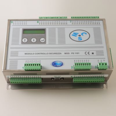
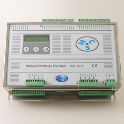
Standard version for electric press brakes.
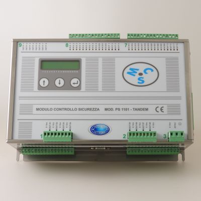
Version for press brakes in TANDEM configuration. In this case you can decide to use the press brakes independently of each other or in tandem, simply by raising the internal mechanical arms.
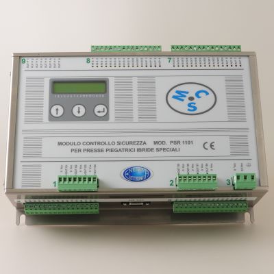
Special version for hybrid press brakes with Hoerbiger system.